PDF Publication Title:
Text from PDF Page: 007
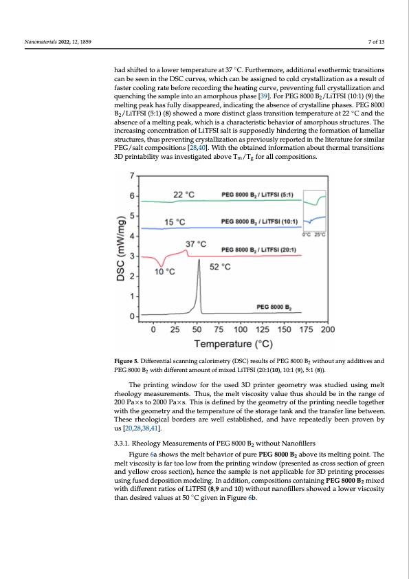
Nanomaterials 2022, 12, 1859 had shifted to a lower temperature at 37 °C. Furthermore, additi tions can be seen in the DSC curves, which can be assigned to result of faster cooling rate before recording the heating curve, pr 7 of 13 tion and quenching the sample into an amorphous phase [39]. (10:1) (9) the melting peak has fully disappeared, indicating th ◦ phases. PEG 8000 B2/LiTFSI (5:1) (8) showed a more distinct glass can be seen in the DSC curves, which can be assigned to cold crystallization as a result of had shifted to a lower temperature at 37 C. Furthermore, additional exothermic transitions at 22 °C and the absence of a melting peak, which is a characte faster cooling rate before recording the heating curve, preventing full crystallization and quenching the sample into an amorphous phase [39]. For PEG 8000 B /LiTFSI (10:1) (9) the 2 phous structures. The increasing concentration of LiTFSI salt is su melting peak has fully disappeared, indicating the absence of crystalline phases. PEG 8000 formation of lamellar structures, thus preventing crystallization a B2/LiTFSI (5:1) (8) showed a more distinct glass transition temperature at 22 ◦C and the absence of a melting peak, which is a characteristic behavior of amorphous structures. The the literature for similar PEG/salt compositions [28,40]. With th increasing concentration of LiTFSI salt is supposedly hindering the formation of lamellar about thermal transitions 3D printability was investigated abov structures, thus preventing crystallization as previously reported in the literature for similar PEG/salt compositions [28,40]. With the obtained information about thermal transitions tions. 3D printability was investigated above Tm/Tg for all compositions. Figure 5. Differential scanning calorimetry (DSC) results of PEG 8000 B without any additives and 2 Figure 5. Differential scanning calorimetry (DSC) results of PEG 8000 B2 PEG 8000 B2 with different amount of mixed LiTFSI (20:1(10), 10:1 (9), 5:1 (8)). PEG 8000 B2 with different amount of mixed LiTFSI (20:1(10), 10:1 (9), 5:1 The printing window for the used 3D printer geometry was studied using melt rheology measurements. Thus, the melt viscosity value thus should be in the range of 200PaT×hsteo2p0r0i0nPtai×nsg. Twhisiinsdeofiwnedfboyrthtehgeeoumseetrdyo3fDthepriinntintegrnegedeloemtogethreyr was with the geometry and the temperature of the storage tank and the transfer line between. ology measurements. Thus, the melt viscosity value thus shoul These rheological borders are well established, and have repeatedly been proven by Puas ×[2s0,2t8o,328,0410].0 Pa×s. This is defined by the geometry of the printing geometry and the temperature of the storage tank and the trans 3.3.1. Rheology Measurements of PEG 8000 B2 without Nanofillers rheoFliogugreic6a lshobwos rthdeemreslt baehraeviowr oef pllurePsEtGab80l0is0 hB2eadb,oveaintsdmelhtinagvpeoinrt.eTpheatedl melt viscosity is far too low from the printing window (presented as cross section of green [20,28,38,41]. and yellow cross section), hence the sample is not applicable for 3D printing processes using fused deposition modeling. In addition, compositions containing PEG 8000 B2 mixed with different ratios of LiTFSI (8,9 and 10) without nanofillers showed a lower viscosity than desired values at 50 ◦C given in Figure 6b. c e F e r s e e w d n fPDF Image | 3D Printable Composite Polymer Electrolytes
PDF Search Title:
3D Printable Composite Polymer ElectrolytesOriginal File Name Searched:
nanomaterials-12-01859-v2.pdfDIY PDF Search: Google It | Yahoo | Bing
Product and Development Focus for Salgenx
Redox Flow Battery Technology: With the advent of the new USA tax credits for producing and selling batteries ($35/kW) we are focussing on a simple flow battery using shipping containers as the modular electrolyte storage units with tax credits up to $140,000 per system. Our main focus is on the salt battery. This battery can be used for both thermal and electrical storage applications. We call it the Cogeneration Battery or Cogen Battery. One project is converting salt (brine) based water conditioners to simultaneously produce power. In addition, there are many opportunities to extract Lithium from brine (salt lakes, groundwater, and producer water).Salt water or brine are huge sources for lithium. Most of the worlds lithium is acquired from a brine source. It's even in seawater in a low concentration. Brine is also a byproduct of huge powerplants, which can now use that as an electrolyte and a huge flow battery (which allows storage at the source).We welcome any business and equipment inquiries, as well as licensing our flow battery manufacturing.| CONTACT TEL: 608-238-6001 Email: greg@salgenx.com | RSS | AMP |