PDF Publication Title:
Text from PDF Page: 010
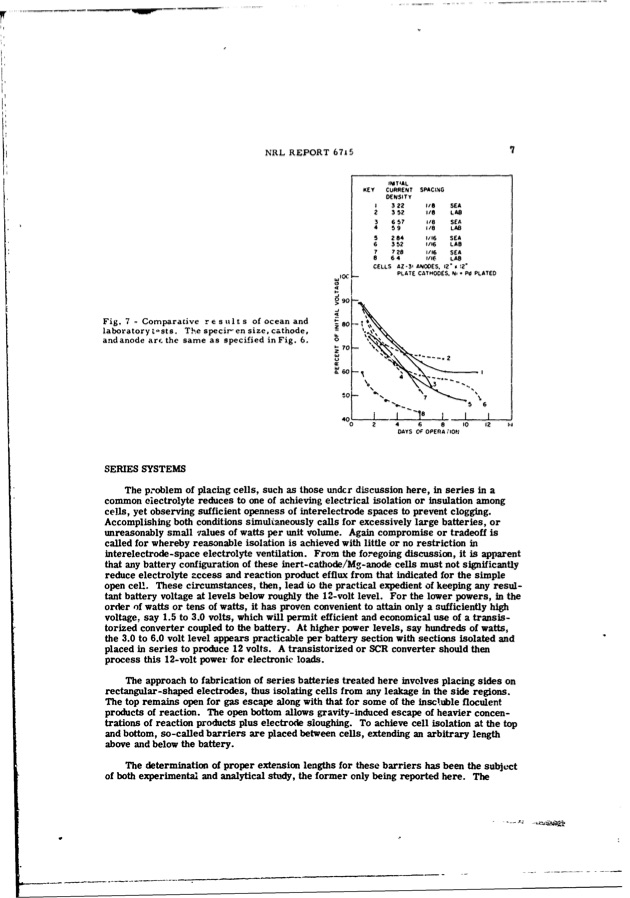
Fig. 7 - Comparative results laboratory t-sts. The specir-en size, cathode, and anode arf the same as specified in Fig. 6. SERIES SYSTEMS NRL REPORT 6715 7 of ocean and The problem of placing cells, such as those undcr discussion here, in series in a common eiectrolyte reduces to one of achieving electrical isolation or insulation among cells, yet observing sufficient openness of interelectrode spaces to prevent clogging. Accomplishing both conditions simultaneously calls for excessively large batteries, or unreasonably small values of watts per unit volume. Again compromise or tradeoff is called for whereby reasonable isolation is achieved with little or no restriction in interelectrode-space electrolyte ventilation. From the foregoing discussion, it is apparent that any battery configuration of these inert-cathode/Mg-anode cells must not significantly reduce electrolyte zccess and reaction product efflux from that indicated for the simple open cell. These circumstances, then, lead to the practical expedient of keeping any resul- tant battery voltage at levels below roughly the 12-volt level. For the lower powers, in the order of watts or tens of watts, it has proven convenient to attain only a sufficiently high voltage, say 1.5 to 3.0 volts, which will permit efficient and economical use of a transis- torized converter coupled to the battery. At higher power levels, say hundreds of watts, the 3.0 to 6.0 volt level appears practicable per battery section with sections isolated and placed in series to produce 12 volts. A transistorized or SCR converter should then process this 12-volt power for electronic loads. The approach to fabrication of series batteries treated here involves placing sides on rectangular-shaped electrodes, thus isolating cells from any leakage in the side regions. The top remains open for gas escape along with that for some of the inscluble floculent products of reaction. The open bottom allows gravity-induced escape of heavier concen- trations of reaction products plus electrode sloughing. To achieve cell isolation at the top and bottom, so-called barriers are placed between cells, extending an arbitrary length above and below the battery. The determination of proper extension lengths for these barriers has been the subject of both experimental and analytical study, the former only being reported here. The WDlC so 0 S90 INITIAL KEY CURRENT SPACING DENSITY ! 322 2352 3 6 57 4 .59 5 284 6 352 7 728 8 64 /8 SEA 1i/ LAO 1/8 SEA 1/8 LAB 1/:6 SEA 1/16 LAB 1/16 SEA 1/16 LAB CELLS AZ-3- PLATE CATHODES. N,' Pd PLATED Q2 .0 Ne7.e • "• 56 40- ANODES. 12" %12' 18 - - 02 4 6 8 10 12 DAYS OF OPERA ;,ONjPDF Image | INERT-CATHODE SEA-WATER BATTERY
PDF Search Title:
INERT-CATHODE SEA-WATER BATTERYOriginal File Name Searched:
AD0673399.pdfDIY PDF Search: Google It | Yahoo | Bing
Product and Development Focus for Salgenx
Redox Flow Battery Technology: With the advent of the new USA tax credits for producing and selling batteries ($35/kW) we are focussing on a simple flow battery using shipping containers as the modular electrolyte storage units with tax credits up to $140,000 per system. Our main focus is on the salt battery. This battery can be used for both thermal and electrical storage applications. We call it the Cogeneration Battery or Cogen Battery. One project is converting salt (brine) based water conditioners to simultaneously produce power. In addition, there are many opportunities to extract Lithium from brine (salt lakes, groundwater, and producer water).Salt water or brine are huge sources for lithium. Most of the worlds lithium is acquired from a brine source. It's even in seawater in a low concentration. Brine is also a byproduct of huge powerplants, which can now use that as an electrolyte and a huge flow battery (which allows storage at the source).We welcome any business and equipment inquiries, as well as licensing our flow battery manufacturing.| CONTACT TEL: 608-238-6001 Email: greg@salgenx.com | RSS | AMP |